Aluminium Sheet Robot
Unfolds the folded aluminium sheets of facade panels from the 3D model, and produces notched, drilled sheets with bend tables, the nesting and the order form.
In training: the robot is being tested on approved past jobs. Files in this field are processed together with an engineer for now; you can still send one for a demo.
- Input
- STEP + XLSX
- Output
- PDF · DWG · XLSX
- Sample run
- 5 sheets ≈ 8 s
- Status
- In training
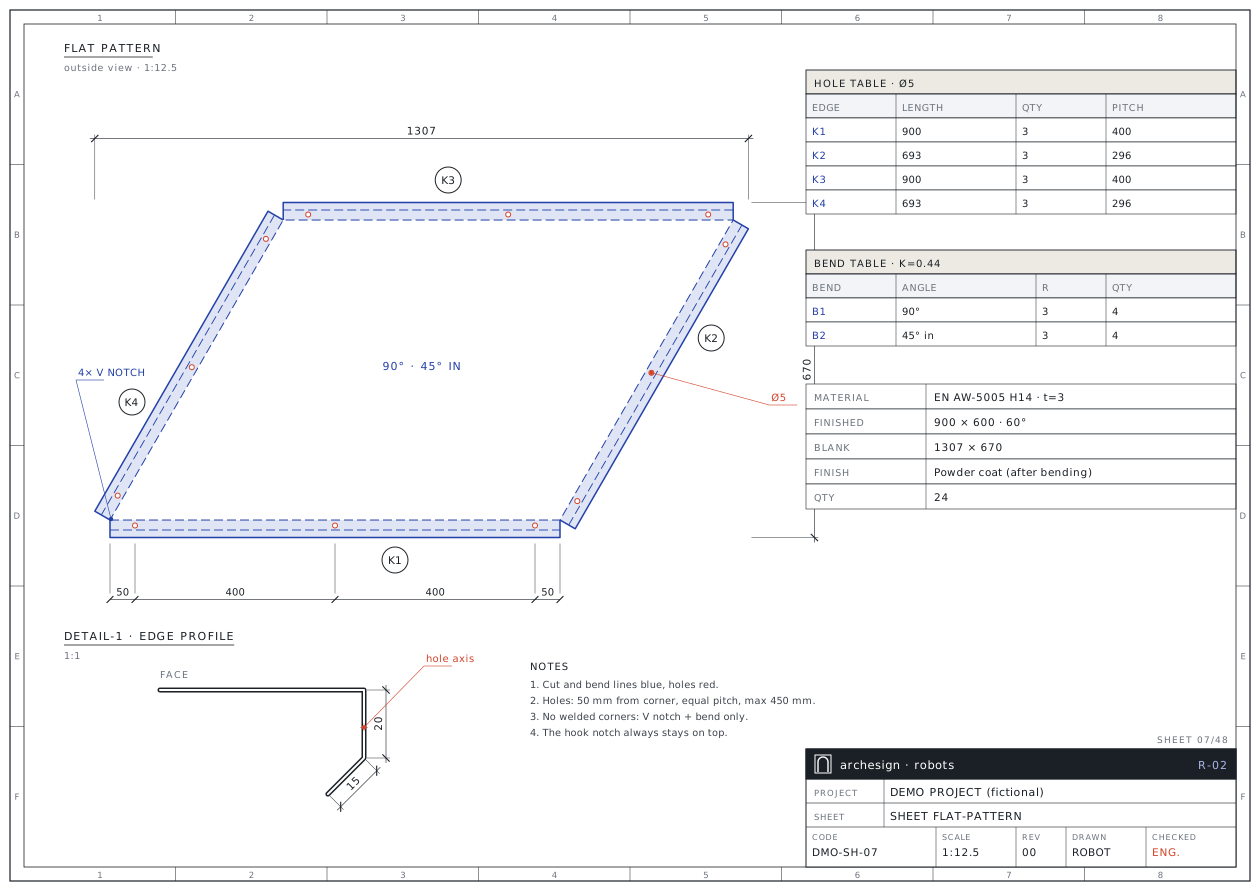
From a 3D sheet to a workshop-ready blank
A facade project has hundreds of folded sheets: trays, cladding, copings, infill panels. Each needs its own flat pattern, bend allowance, corner notch and hole row, and many are parallelograms or multi-bend parts.
The Aluminium Sheet Robot reads the sheet model; a surface model without thickness is enough. It finds the face, flanges and lips, and computes the flat pattern with bend formulae. It cuts a V notch at the corners for the laser and places holes to the standard. One A3 sheet per type holds the flat pattern, sections, details and tables.
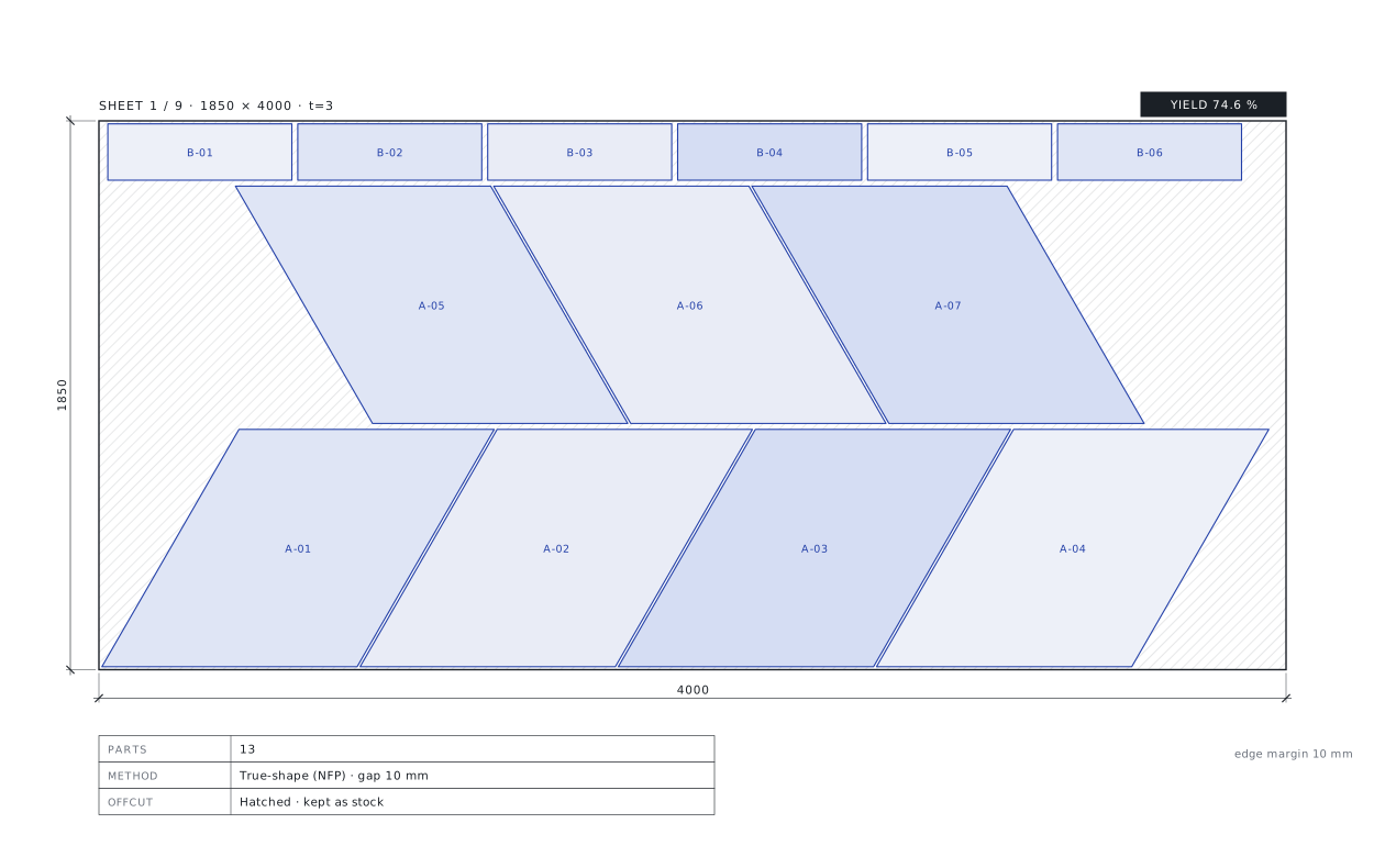
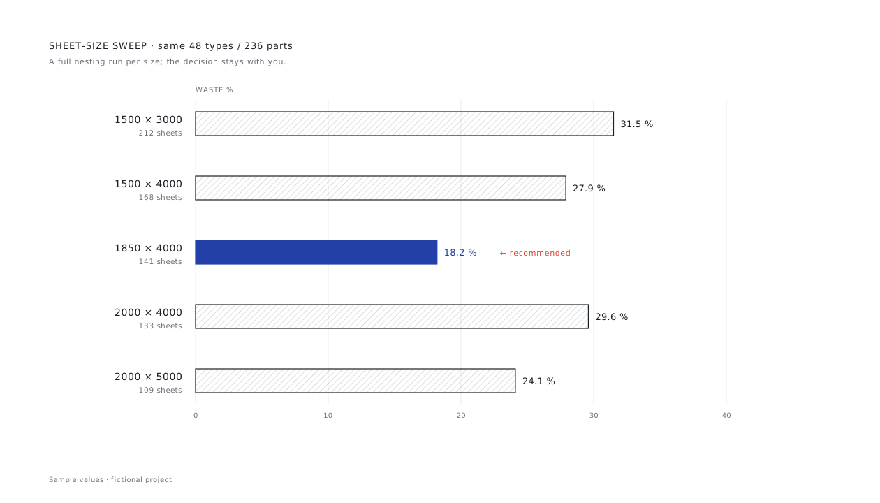
If you buy the material, the robot sweeps sheet sizes and nests the parts by their true outline. You see how many sheets of which size you need, and how much waste, before you order.
What you send, what you get back
Your files come in as they are; the output goes out in the form the workshop, purchasing and site teams use directly.
You send
- STEPSheet typesOne file per type; a surface model is enough, no thickness needed.
- XLSXQuantity and colour listCode, quantity, parent panel, material and paint colour.
- DWG2D blank, if anyIf you only have blanks, it works from the outline and edge profiles.
You get
- PDFOne A3 sheet per typeFlat pattern, section, edge-profile and corner details, bend and hole tables.
- DWG1:1 DXF / DWGSeparate cut, bend and hole layers for the laser.
- XLSXFabrication list + work requestBlank size, m², kg and finish, in your own form template.
- NESTNesting (optional)Sheet-size sweep, sheet count, yield and the order form.
What the robot does, step by step
Blue steps are run by the robot. The red step is a facade engineer's check, and no set is delivered without it.
Finds the rules and templaterobot
Sheet rules and an approved sister set come first; only job-specific differences are adapted.
Reads the modelrobot
The largest plane is the face; flanges, lips and steps are chained by adjacency and model noise is rounded off.
Sets the orientationrobot
Sheets are drawn from outside. If the hook notch ends up at the bottom, the part is turned 180° and noted.
Computes the flat patternrobot
Bends towards the material and reverse (Z) bends use their own formulae; bend zones are generated separately.
Cuts corners and holesrobot
Weld-free V notches; Ø5 holes 50 mm from corners, equal pitch, max 450 mm, in the flat part of the flange.
Lays out and verifiesrobot
One A3 per type, dimensions outside the blank. Dimensions, hole positions and totals are checked by program.
An engineer checksengineer
View direction, painted side and open questions are reviewed, against the building model if needed.
Writes the package and orderrobot
List and work request; nesting and sheet order on request. In a revision-numbered folder.
This is what the output looks like
The drawings below come from a fictional demo project. Real client drawings and codes are never shown here.
Forms and lists come ready too
Rows follow the sheet order; blank size and finish go straight to the workshop.
| Code | Panel | Qty | W | L | m² | kg | Finish |
|---|---|---|---|---|---|---|---|
| DMO-SH-01 | P-03 | 24 | 1307 | 670 | 21.02 | 170.3 | RAL 7016 |
| DMO-SH-02 | P-03 | 24 | 1180 | 640 | 18.12 | 146.8 | RAL 7016 |
| DMO-SH-07 | P-05 | 12 | 1520 | 702 | 12.80 | 103.7 | Mill |
| DMO-SH-11 | P-08 | 36 | 968 | 455 | 15.86 | 128.4 | RAL 7016 |
| Total | 96 | 67.80 | 549.2 |
Rules applied to every set
The rules come from 19 years of facade fabrication and from approved sets. Each rule is numbered and linked to the code and to the check report.
- Weld-free corners: one notched blank and bends; closed-ring blanks that a press brake cannot form are never used.
- Hole standard: Ø5, 50 mm from corners, equal pitch, max 450 mm; hole in the middle of the flat flange zone.
- Short flanges: under 150 mm one central hole, under 40 mm no hole.
- Sheets are drawn from outside; painted face and flange direction follow the panel position.
- The hook notch is always on top; a model turned upside down is caught automatically.
- All dimensions outside the blank; cut and bend in blue, holes in red.
- Painting after bending; painted and mill faces are marked separately in the list.
- The sheet size is your decision: the robot compares the options by sheet count and waste.
Fifty types in minutes
With the rules in place, fifty types are calculated and drawn in minutes; the real time goes into answering questions.
* Manual time is an estimate. Other figures are rounded from real jobs; project names are never shown.
Whose work this robot makes easier
- 01
Facade engineering teams
Check blanks instead of drawing them.
- 02
Laser and press-brake shops
Cut straight from a layered 1:1 DXF.
- 03
Purchasing
See how many sheets of which size to buy, with the waste rate.
- 04
Subcontract coordinators
Sheets, lists and work requests ready for jobs placed with material.
Send your first file to the robot
Send one assembly, one sheet type or one bid package. We send back the sample output and a quote for the full job.
- 01Your first file is processed free of charge as a sample.
- 02After reviewing the output you get a quote for the full job.
- 03Your files stay confidential and are used for your job only.
- 04We can work with your own title block and layer standard.
Frequently asked questions
Which model do you need?
One STEP per type and a quantity/colour list. A surface model is fine; no thickness needed. If you only have 2D blanks, it works from the face outline and edge profiles.
How is the bend allowance calculated?
By the OSSB/BA/BD method with inner R = t and K = 0.44 by default. If your press brake differs, the parameter is changed, the set rebuilt and a note added.
Are the corners welded?
No. A laser-friendly V notch is cut at each corner; the part is only bent.
What if the model faces the wrong way?
A part turned 180° is detected from the hook-notch position, drawn the right way round and noted.
Does it also produce the sheet order?
If you buy the material, yes: size sweep, true-shape nesting, sheet count, waste and the order form. For jobs placed with material, this step is skipped.