Steel Anchor Robot
From the 3D model of your anchor assemblies and the BOM spreadsheet to a workshop-ready A3 set, with welds, hole dimensions and material packages sorted.
- Input
- STEP + XLSX
- Output
- PDF · DWG · XLSX
- Sample run
- 43 sheets ≈ 6 min
- Status
- Ready
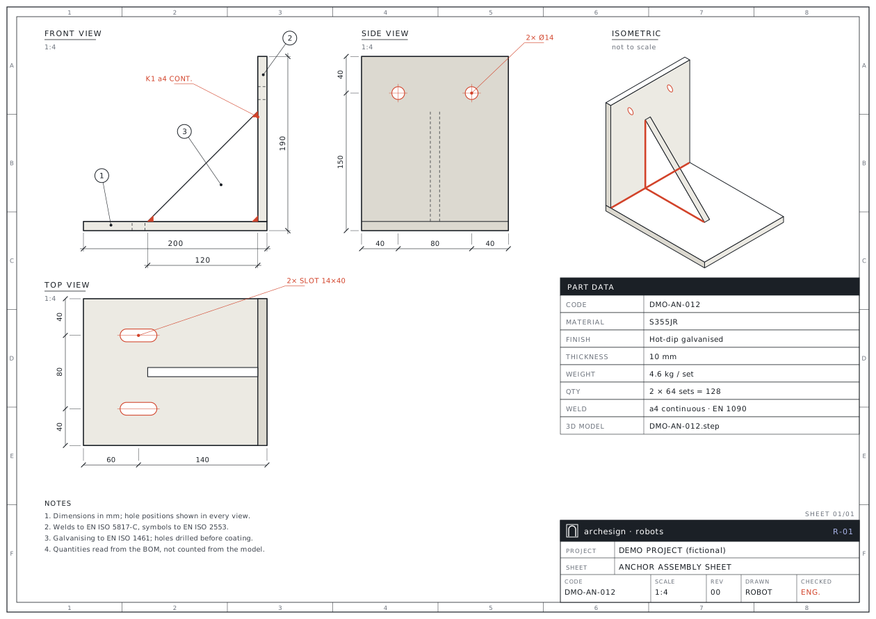
From assembly model to workshop sheet
Facade anchors are small but have many parts: plates, stiffeners, washers, studs. Each part needs its own sheet, weld, hole dimensions and quantity. This is where most mistakes happen when drawn by hand.
The Steel Anchor Robot splits the assembly into parts and recognises each one. It measures thickness, holes, slots, bends and weld corners from the geometry. Quantities and materials are read from the BOM, never counted from the model. The result: assembly and part sheets, laser-cutting DXF, work and material request forms, and a check report.
It never produces a part it is unsure about. It comes back to you with a question and a proposal, and completes the set once you answer.
What you send, what you get back
Your files come in as they are; the output goes out in the form the workshop, purchasing and site teams use directly.
You send
- STEPAnchor assembliesOne assembly per anchor, plus single-part files if available. Unnamed solids are fine.
- XLSXBOM and set quantitiesQuantity per set, material, project totals and fixings.
- TXTShort job cardJob number, requester, finish (galvanised / painted) and notes.
You get
- PDFA3 fabrication setCover, fixings summary, assembly and part sheets, flat patterns, cutting list.
- DWG1:1 DXF / DWGMeasurable model; CUT / HOLE / BEND layers for the laser.
- XLSXWork and material requestsWidth, length, quantity and weight per part; raw material in kg by grade and thickness.
- PDFCheck reportWarnings, open questions, rule numbers and revision differences.
What the robot does, step by step
Blue steps are run by the robot. The red step is a facade engineer's check, and no set is delivered without it.
Receives the filesrobot
Jobs from the form or a shared folder are queued and start once the upload is complete.
Reads and names the modelrobot
Builds a volume signature from the single parts and uses it to recognise unnamed solids in the assembly.
Takes quantities from the BOMrobot
Quantity = BOM × number of sets, checked against the project total; any conflict becomes a question.
Measures the geometryrobot
Thickness, holes, slots, bends and weld corners come from the faces; serrated faces are told apart from welds.
Draws views and sectionsrobot
Visible lines are computed edge by edge; sections pass through hole centres.
Lays out the sheetsrobot
Title block, dimension chains, balloons and the part data card, with zero text clashes.
An engineer checksengineer
The check report and questions are reviewed; answers are applied and the set completed.
Delivers the packagerobot
A revision-numbered folder: PDF, DXF/DWG, laser DXF, forms and the check report.
This is what the output looks like
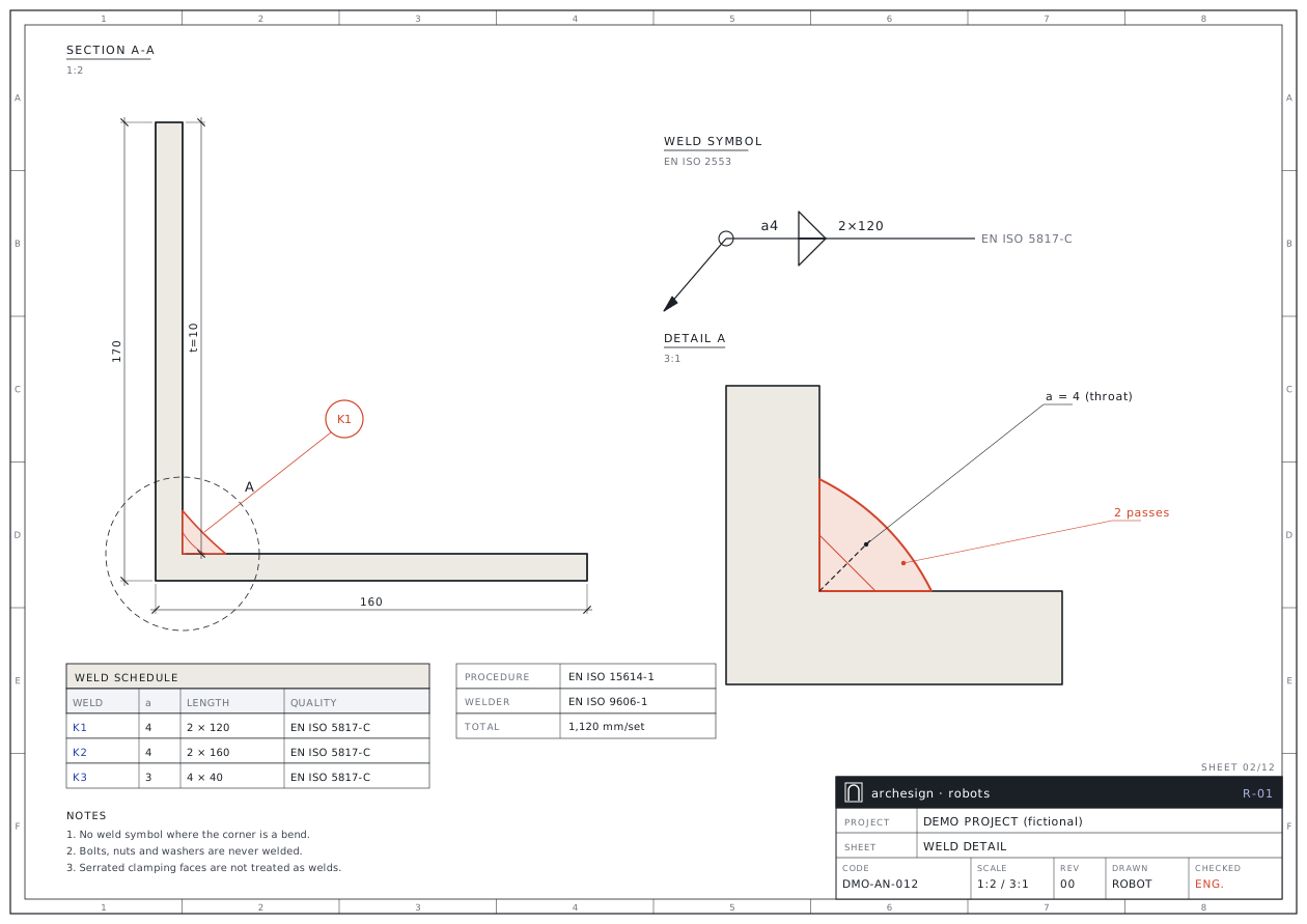
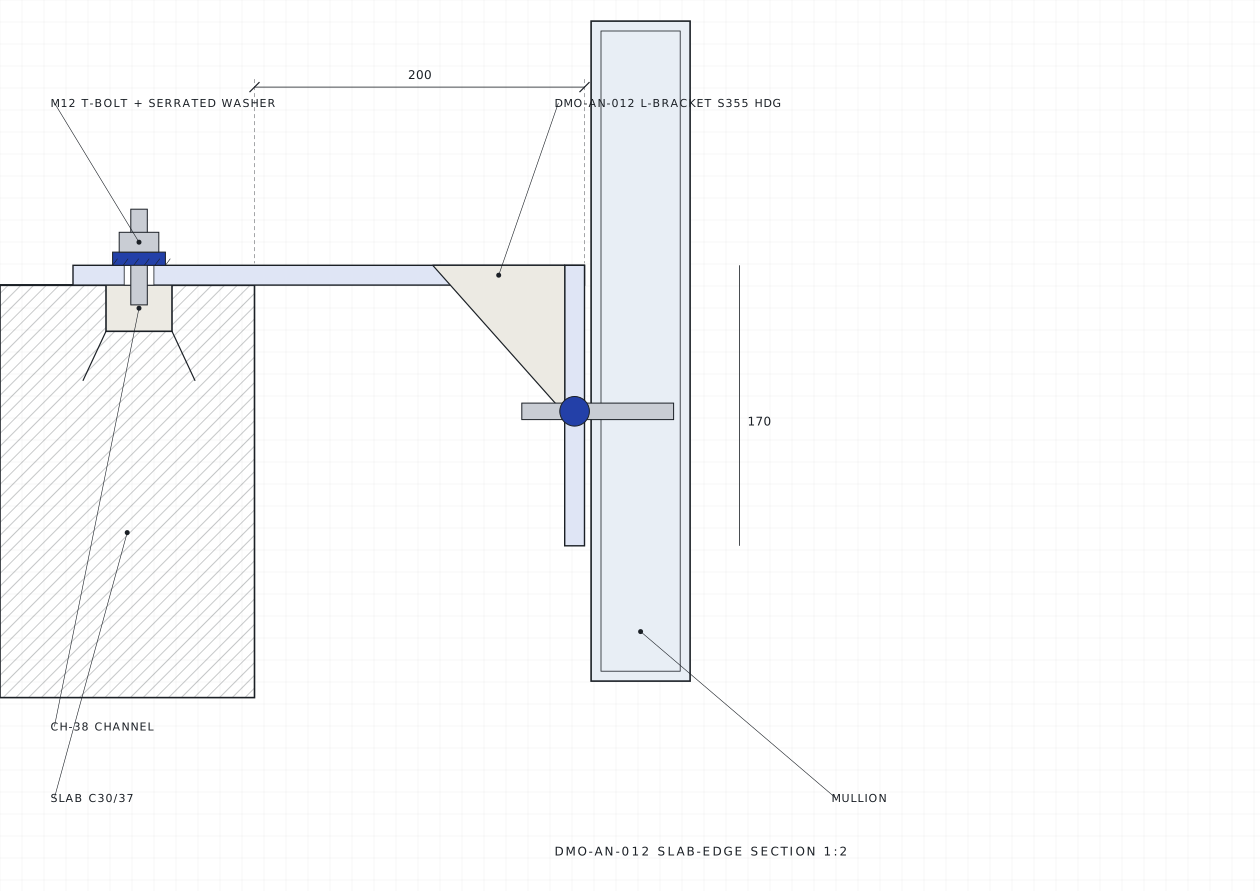
The drawings below come from a fictional demo project. Real client drawings and codes are never shown here.
Forms and lists come ready too
Parts are listed with their sheet numbers; raw material is totalled on a separate tab in kg by grade and thickness.
| Item | Description | Material | t | W × L | Qty | kg/pc | Sheet |
|---|---|---|---|---|---|---|---|
| AN-012-01 | Base plate | S355JR | 10 | 200 × 160 | 128 | 2.51 | 04 |
| AN-012-02 | Upstand | S355JR | 10 | 180 × 160 | 128 | 2.26 | 05 |
| AN-012-03 | Stiffener | S235JR | 10 | 120 × 120 | 128 | 0.57 | 06 |
| AN-014-01 | Adjustment plate | S235JR | 8 | 140 × 90 | 64 | 0.79 | 07 |
| AN-014-02 | Square washer | S235JR | 5 | 50 × 50 | 256 | 0.10 | CONFIRM |
| Total | 704 |
Rules applied to every set
The rules come from 19 years of facade fabrication and from approved sets. Each rule is numbered and linked to the code and to the check report.
- When unsure, stop and ask: an uncertain part is not produced; with an open question the set is stamped "incomplete".
- Hole dimensions in every view: qty × Ø or SLOT a×b callout plus two-axis dimensions from the edges.
- Part code and quantity in every view; plates also show material and thickness.
- Sections pass through hole centres; heavy outline, light detail, no fills.
- Welds drawn to the standard; bolts, nuts and washers never get a weld symbol.
- Steel, aluminium and PVC in separate packages; the steel package goes straight to the external shop.
- Zero text clashes or no delivery.
- The REV number changes together in the file name, title block and forms.
Minutes of run time instead of weeks of drawing
An approved 43-sheet set was rebuilt by the robot and every number matched.
* Manual time is an estimate. Robot times come from rebuilding a real approved set; delivery time depends on the number of questions and the check.
Whose work this robot makes easier
- 01
Facade contractors
The engineering team checks sheets instead of drawing them.
- 02
External steel shops
Start fabrication directly from the laser DXF and material package.
- 03
Precast and GRC producers
Series sheets for embedded and hanging anchors.
- 04
Design offices
A measurable fabrication set to attach to the construction drawings.
Send your first file to the robot
Send one assembly, one sheet type or one bid package. We send back the sample output and a quote for the full job.
- 01Your first file is processed free of charge as a sample.
- 02After reviewing the output you get a quote for the full job.
- 03Your files stay confidential and are used for your job only.
- 04We can work with your own title block and layer standard.
Frequently asked questions
What if the parts in the model have no names?
A volume signature is built from the single-part files and used to name the unnamed solids. Unmatched solids are treated as fixings; anything still uncertain is sent to you as a question.
How does it know where the welds are?
It measures concave sharp corners along the edges and filters out bends, serrated clamping faces and bolts. If the design does not define a weld, the assumption is written on the sheet with a "confirm" note.
Does it count quantities from the model?
No. Quantities and materials are read from the BOM spreadsheet; the model is only geometry. If they disagree, a question is raised.
Which formats do you deliver?
A single PDF set, 1:1 DXF, DWG, laser-cutting DXF, STEP, Excel forms and the check report.
Can you use our own title block?
Yes. On the first job we take your title block and layer list; every later set follows them.