Galvanised Sheet Robot
Unfolds the galvanised back trays of facade panels and draws them with corner notches and holes. Finds parts that do not fit the coil, proposes a splice and optimises the coil or sheet order.
In training: the robot is being tested on approved past jobs. Files in this field are processed together with an engineer for now; you can still send one for a demo.
- Input
- DWG / STEP + XLSX
- Output
- PDF · DWG · XLSX
- Sample run
- 56 pages ≈ 25 s
- Status
- In training
Closes the gap between part and coil
The galvanised tray is the hidden part of a panel that eats the most material. Its blank and holes follow the same rules as aluminium sheet; the real difficulty is supply. Coil widths are limited, slanted parts may not fit, and standard sheets drive waste up.
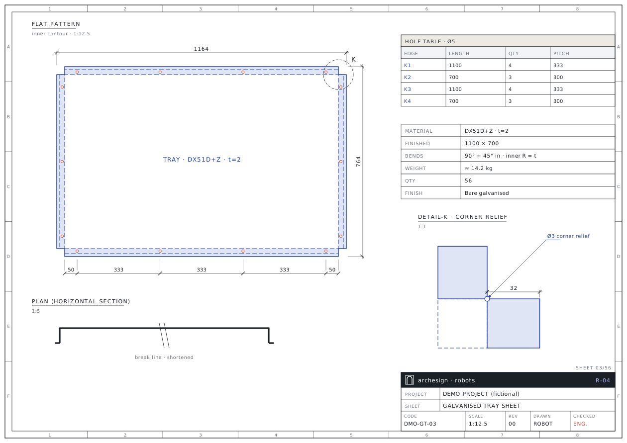
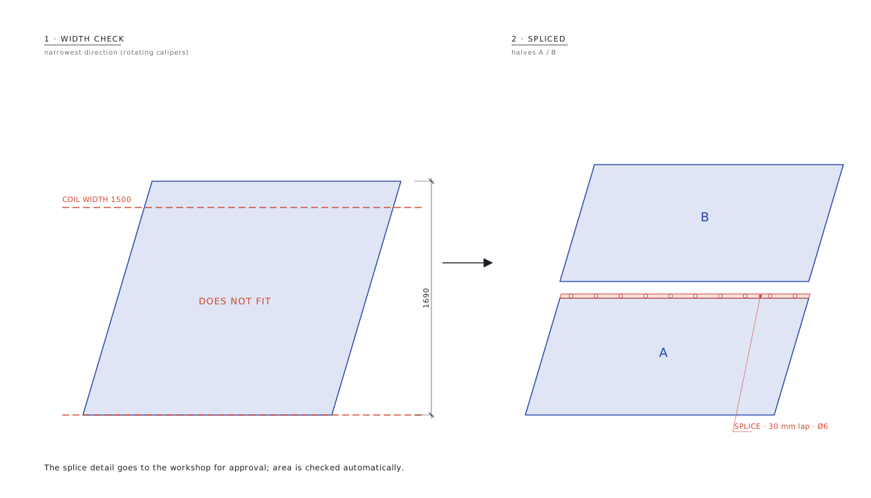
The Galvanised Sheet Robot unfolds trays from DWG or STEP and draws one A3 sheet per type. It computes the narrowest width of every part and lists those that do not fit the coil. For them it compares wide coil, black steel + hot-dip galvanising or a spliced part, by count and m².
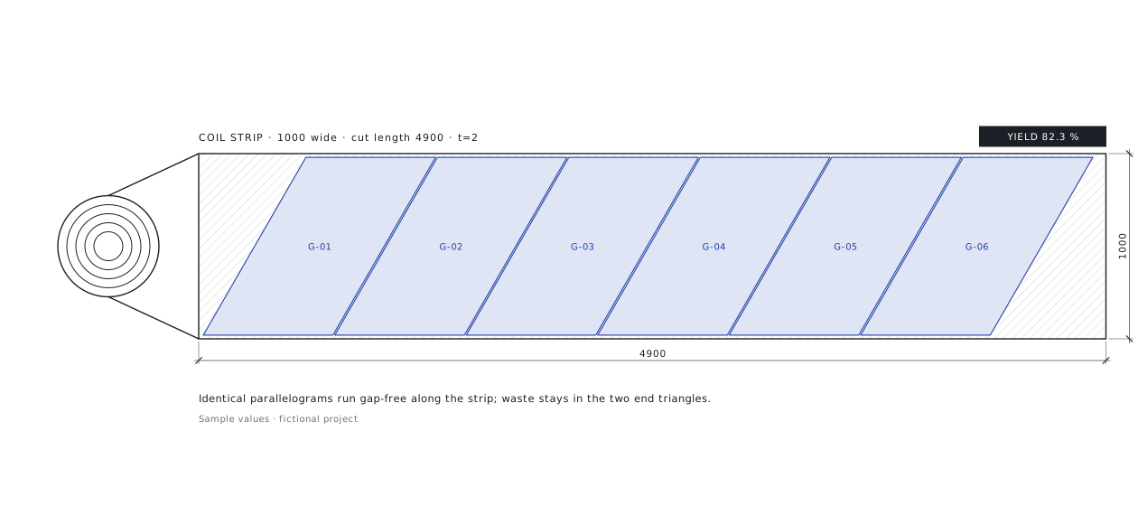
Identical parallelograms run gap-free along the coil strip; mixed types are shelf-packed. For coil cut-to-length it computes each sheet's own length, and the order summary comes as sheet or coil count, m² and kg.
What you send, what you get back
Your files come in as they are; the output goes out in the form the workshop, purchasing and site teams use directly.
You send
- DWGBlank drawingWith cut and bend layers, plus a quantity and thickness list.
- STEPOr a 3D modelGoes through the same unfolding engine as aluminium sheet.
- DWGSample sheet (optional)Hole pitch and profile rules are taken from your own example.
You get
- PDFOne A3 sheet per typePlan and section, flat pattern, edge profile and corner detail, tables.
- NESTOptimisation sheetFull and offcut sheet layouts, pattern table, order comparison.
- XLSXDoes-not-fit analysisNarrowest strip per part; count and m² difference per option.
- XLSXOrder summary + formsSheet/coil count, m², kg; work and material request forms.
What the robot does, step by step
Blue steps are run by the robot. The red step is a facade engineer's check, and no set is delivered without it.
Reads the sourcerobot
Bend segments are chained into ordered polygons; unreadable files are listed separately.
Builds the profilerobot
The outer surface chain is the reference. A reversed chain would silently turn outer into inner dimensions; the robot catches it.
Computes blank and cornerrobot
Inner R = t, K = 0.44; notches with different wedge angles at narrow and wide corners.
Places the holesrobot
Ø5, 50 mm from the ends, equal pitch, max 450 mm; inner bends are never drilled.
Checks the coil widthrobot
The narrowest direction of each part is found; misfits are reported and a splice line proposed when needed.
Nests the partsrobot
Identical parallelograms gap-free in strips, mixed types shelf-packed; 10 mm edges and gaps.
An engineer checksengineer
Splice detail, coil/sheet choice and shop rules are confirmed with you.
Writes order and formsrobot
Optimisation sheet, order summary and request forms under a REV number.
This is what the output looks like
The drawings below come from a fictional demo project. Real client drawings and codes are never shown here.
Forms and lists come ready too
Options side by side for the same part list: sheet count, m², weight and yield.
| Option | Size / coil | Qty | m² | Tonnes | Yield | Note |
|---|---|---|---|---|---|---|
| A | 1500 × 5400 sheet | 152 | 1,231 | 19.3 | 60 % | 9 types too wide → splice |
| B | 1830 × 6200 sheet | 76 | 862 | 13.5 | 85 % | From imported coil |
| C | 1000 coil · cut to length | 98 | 805 | 12.6 | 91 % | Coil, 6000 table |
Rules applied to every set
The rules come from 19 years of facade fabrication and from approved sets. Each rule is numbered and linked to the code and to the check report.
- Weld-free tray: one notched blank and bends; if a closed corner is needed, the weld is specified separately.
- Same hole standard as aluminium: Ø5, 50 mm, equal pitch, max 450 mm; outer edge flanges only.
- Reverse (Z) bends use their own formula; inner bends are never drilled.
- Coil width check: the narrowest strip of every part is computed; a misfit never slips through.
- A splice is a design decision: the robot proposes; lap, holes and butyl tape go to the workshop for approval.
- No guillotine on slanted outlines; cutting is by CNC plasma or laser.
- Extra width is waste: a wider sheet is not always better; options are compared by calculation.
- Independent verification: outline dimensions in the DXF are measured again.
The coil decision, before the order
A single-type set with optimisation and forms was finished in two deliveries on one day; a 56-type set with splices, nesting and forms was set up in one day.
* Manual time is an estimate. Other figures are rounded from real jobs.
Whose work this robot makes easier
- 01
Facade factories
Back-tray sheets and the order in one package.
- 02
Sheet-metal shops
1:1 DXF and strip plans for plasma and laser.
- 03
Purchasing
Compare coil, sheet and splice options in tonnes and m².
- 04
Planning
See the misfits before fabrication starts.
Send your first file to the robot
Send one assembly, one sheet type or one bid package. We send back the sample output and a quote for the full job.
- 01Your first file is processed free of charge as a sample.
- 02After reviewing the output you get a quote for the full job.
- 03Your files stay confidential and are used for your job only.
- 04We can work with your own title block and layer standard.
Frequently asked questions
What if a part does not fit the coil?
The narrowest strip it needs is computed and listed. Wide coil, black steel + hot-dip galvanising or a spliced part are compared by count, m² and tonnes.
How is a splice made?
The part is split along its line of symmetry; a flat lap, holes and butyl tape are proposed. The detail goes to the workshop for approval and area conservation is checked automatically.
What is the strip method?
Identical parallelograms run gap-free along one strip; waste stays only at the strip ends and in the leftover band.
What if the bend allowance differs from our shop's?
The robot uses the physical method (inner R = t, K = 0.44); switching to your shop's inner-contour rule is one parameter, and the difference is noted on the sheet.
Are hole and notch rules the same as for aluminium?
Yes, the shared sheet rules apply: Ø5 holes, 50 mm from corners, equal pitch; the hook notch on top.