Profile Robot
Produces the complete set for the workshop and the CNC from the 3D model of facade profile units: sheets, drilled CNC files, cut optimisation and an ERP-coded bill of materials.
- Input
- STEP + XLSX
- Output
- PDF · DWG · STEP · XLSX
- Sample run
- 82 pages ≈ 100 s
- Status
- Ready
The whole profile: sheets, CNC and BOM
A transom or mullion unit is never a single profile: it comes with an isolator, gaskets, setting blocks, sheets, angles and fixings. Each one needs the right notch, hole, cut length and stock code.
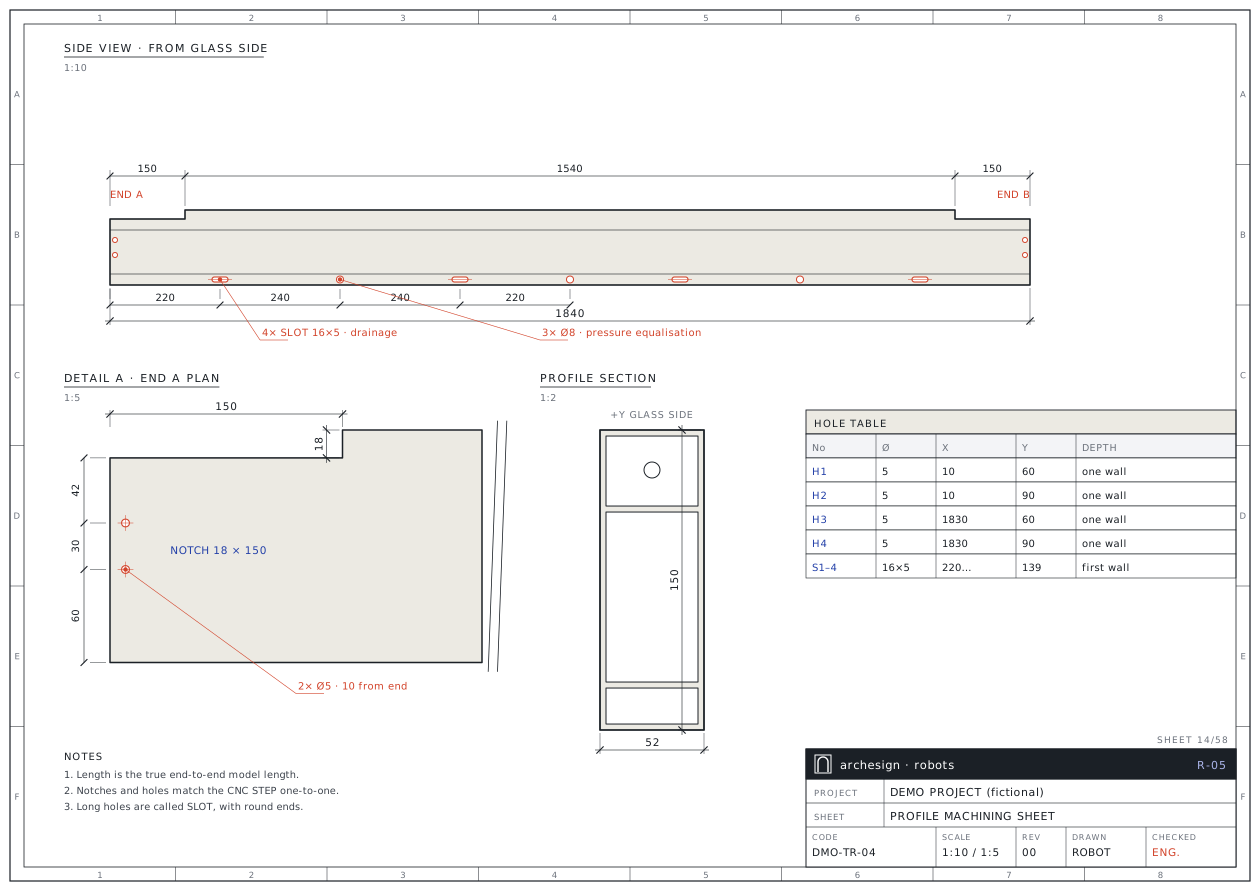
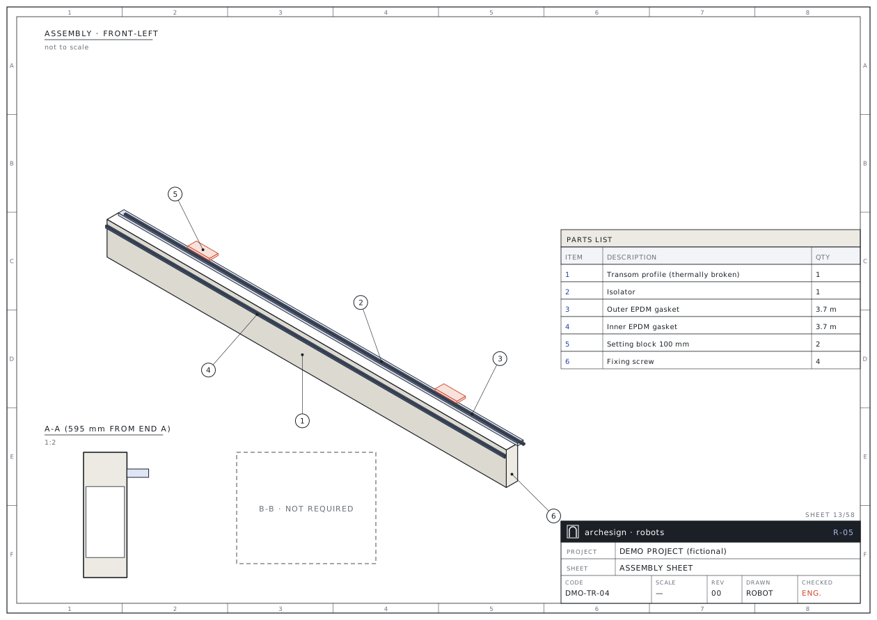
The Profile Robot reads the unit model and classifies the parts. It aligns the profile with its extrusion axis and takes notches and holes from the real geometry. For each unit it lays out assembly, two elevations, profile machining, sheet blank and cutting pages in a single PDF set. The last page of the set is the total bill of materials.
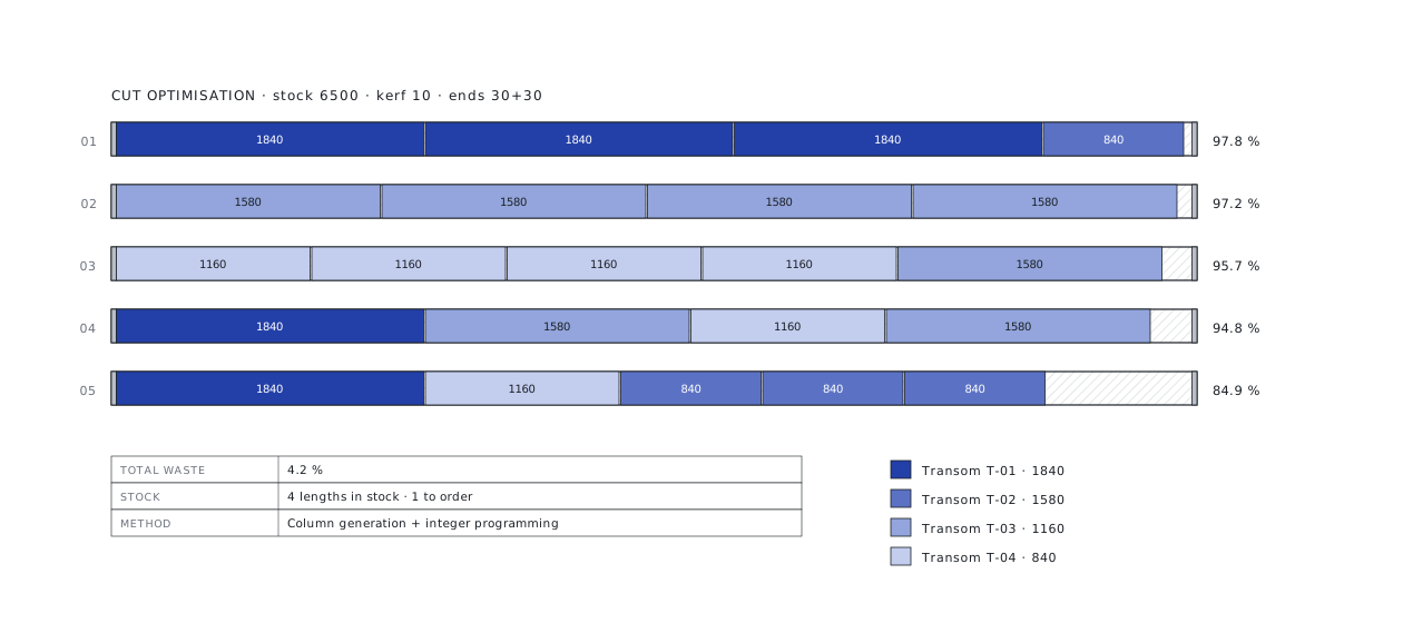
For every part it writes a CNC STEP with the holes truly cut and the part placed in the machine frame, identical to the hole list on the sheet. Cuts are optimised over stock lengths; lengths not in stock go to the order list.
What you send, what you get back
Your files come in as they are; the output goes out in the form the workshop, purchasing and site teams use directly.
You send
- STEPUnit modelsTransom or mullion assembly with part names in the model. Unnamed parts are recognised by geometry signature.
- XLSXUnit quantitiesWork request or assembly table; quantities come from here.
- PDFSystem sheets (optional)The system supplier's machining rules; holes missing from the model are added from them.
You get
- PDFFabrication set per unitAssembly, elevations from the glass and room side, profile machining, sheet blank, cutting.
- STEPDrilled CNC filesPer part and per unit; straight to the profile machining centre.
- XLSXERP-coded BOMTotal BOM and unit detail; codes without an ERP match marked CONFIRM.
- NESTCut optimisationCutting patterns over stock lengths, sheet nesting and the order list.
What the robot does, step by step
Blue steps are run by the robot. The red step is a facade engineer's check, and no set is delivered without it.
Reads and inventoriesrobot
Part names, colours and the assembly tree are read; per part: quantity, oriented box and volume.
Classifiesrobot
Profile, isolator, gasket, block, sheet, angle, steel and fixings; a unit without a main profile becomes a question.
Verifies quantitiesrobot
Quantity = per unit × number of units. If table and model disagree, the part is not produced but asked about.
Aligns to the axisrobot
Length on X, section on Y/Z. The extrusion axis comes from side-face area, not the longest dimension.
Extracts machiningrobot
Notch zones are measured at three stations, holes from cylindrical faces; missing assembly holes come from the supplier's rule.
Lays out the sheetsrobot
Edge-based visible lines; dimension chains from part edges, zero text clashes.
Optimises cuttingrobot
One-dimensional cutting by integer programming; stock read from the warehouse list, missing lengths go to the order.
An engineer checksengineer
Pages are scanned as images and by program; hole count and callout count are compared in every view.
This is what the output looks like
The drawings below come from a fictional demo project. Real client drawings and codes are never shown here.
Forms and lists come ready too
The BOM is matched to ERP stock codes; items without a match are marked CONFIRM. Nothing is written to the ERP; it is only read from a copy.
| Material code | Description | Material | ERP stock | Qty | Length (m) | kg |
|---|---|---|---|---|---|---|
| PR-T150 | Transom profile 150 (thermally broken) | Al 6063 T6 | AL.0150.T | 61 | 98.6 | 312.4 |
| IS-26 | Isolator | PVC | PV.0026 | 61 | 98.6 | 24.7 |
| GS-04 | EPDM gasket, outer | EPDM | EP.0004 | — | 206.0 | 18.5 |
| SB-100 | Setting block 100 mm | PP | PP.0100 | 122 | — | 1.2 |
| SC-0525 | Fixing screw | A2 | CONFIRM | 244 | — | 2.0 |
| Total | 358.8 |
Rules applied to every set
The rules come from 19 years of facade fabrication and from approved sets. Each rule is numbered and linked to the code and to the check report.
- Orthographic views; the 3D view is always front-left, from the glass side.
- Callout = material code + part code; no descriptive text on the drawing.
- A long hole is a SLOT; drawn with round ends, milled, never sawn.
- Every item drawn on the cutting sheet: profile, isolator, gasket and blocks included.
- Kerf 10 mm; 30 + 30 mm end trim only on painted profiles.
- A thermally broken profile is one composite item; frame corners 45° mitred, intermediate transoms butt-jointed.
- Finish comes from the work request; no default finish is assumed.
- The ERP is only read from a copy; nothing is ever written to it.
Minutes, not weeks
A 22-unit transom set came out as one 82-page file; on the second delivery, with a warm cache, the run took about 100 seconds.
* Manual time is an estimate. Other figures are rounded from real jobs.
Whose work this robot makes easier
- 01
Facade engineering teams
Issue the per-unit fabrication set after checking it.
- 02
Profile shops and CNC
Drilled STEP files shorten programming.
- 03
Planning and purchasing
BOM, stock and order list from the same package.
- 04
Site and QA
Track parts with the assembly page and parts list.
Send your first file to the robot
Send one assembly, one sheet type or one bid package. We send back the sample output and a quote for the full job.
- 01Your first file is processed free of charge as a sample.
- 02After reviewing the output you get a quote for the full job.
- 03Your files stay confidential and are used for your job only.
- 04We can work with your own title block and layer standard.
Frequently asked questions
Which files do you need?
One STEP per unit (with part names inside) and a spreadsheet of unit quantities. The finish goes on the job card.
What if the model and the table disagree?
The robot does not produce that part, lists it as a question and stamps the set "incomplete, not for fabrication". Once answered, the same revision is completed.
What goes to the CNC?
Per part: a single-solid STEP with holes and notches truly cut, placed in the machine frame with the section parallel to the floor. It matches the hole list on the sheet one-to-one.
What if the model has no holes?
They are added from the supplier's assembly rule and the screw/bolt axes in the model; depth is measured from the real wall.
How is cutting waste calculated?
Kerf 10 mm; 30 + 30 mm end trim only on painted profiles. Length is the true end-to-end model length, and cut angles are respected.