Stick Facade Robot
From a simple sketch of grids and levels it builds a 3D facade model with the chosen stick system's real catalogue sections, and produces shop drawings, profile fabrication sheets and the order list.
In training: the robot is being tested on approved past jobs. Files in this field are processed together with an engineer for now; you can still send one for a demo.
- Input
- Sketch DWG + catalogue
- Output
- STEP · PDF · DWG · XLSX
- Example
- 158 solids ≈ 2 s
- Status
- In training
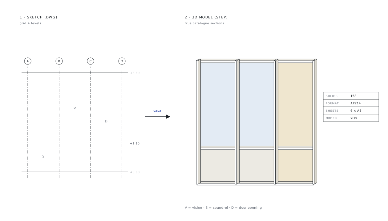
From a few lines to an orderable facade
On small and mid-size stick curtain wall jobs, most of the time goes into translating architectural lines into the system's language: mullion and transom sections, glass and gasket choice, cut lengths, accessories and the order.
The Stick Facade Robot reads grids, levels and cell types from a sketch. It takes the chosen system's profile sections from the supplier's own drawings and applies cut formulae, gasket and setting-block tables from the catalogue. The result is a 3D model with real sections, shop drawings and profile fabrication sheets.
It checks glass weight with the supplier's calculation tool and optimises profiles over stock bar lengths; gaskets come in metres, accessories in pieces, glass in m². For larger facades, a set-out module produces the layout sheet of elevation, sections and plans.
What you send, what you get back
Your files come in as they are; the output goes out in the form the workshop, purchasing and site teams use directly.
You send
- DWGFacade sketchMullion grids, transom levels and cell types (vision / spandrel / door).
- PDFSystem catalogueCut formulae, gasket and setting-block tables, hole positions.
- DWGProfile sectionsThe supplier's mullion and transom section drawings.
You get
- STEP3D facade modelSolids with real sections, plus a DWG preview.
- PDFShop drawings + fabricationElevation, section, plan and nodes; mullion and transom fabrication sheets.
- XLSXOrder listProfiles (bar-optimised), gaskets, accessories, glass, spandrel, workshop cutting list.
- XLSXFormsInternal work order and external material order, with PDFs.
What the robot does, step by step
Blue steps are run by the robot. The red step is a facade engineer's check, and no set is delivered without it.
Reads the sketchrobot
Grid x values, level z values and cell labels go into one system-constants file.
Sets up the systemrobot
The catalogue is searched by article number; pressure plate, setting block and gasket set follow the glass thickness.
Checks glass weightrobot
The supplier's calculation tool runs on a copy; exceeding the limit raises a warning.
Takes the real sectionrobot
Outline and voids of the section drawing are read and simplified; derived dimensions are cross-checked with the drawing.
Builds the 3D modelrobot
Sections are extruded, the STEP written and read back for verification; kg/m comes from the section area.
Produces lengths and sheetsrobot
Cut lengths from catalogue formulae; sheets in your layer standard with an A3 title block.
Optimises the orderrobot
Profiles nested on stock bars; gaskets in m, accessories in pcs, glass in m²; forms in your template.
An engineer checksengineer
Assumptions and "needs checking" items (glass weight, anchor type, colour) are confirmed with you.
This is what the output looks like
The drawings below come from a fictional demo project. Real client drawings and codes are never shown here.
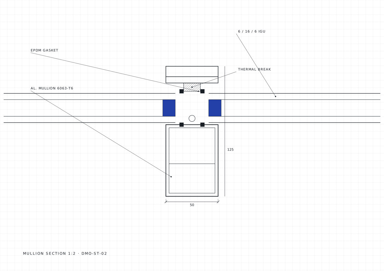
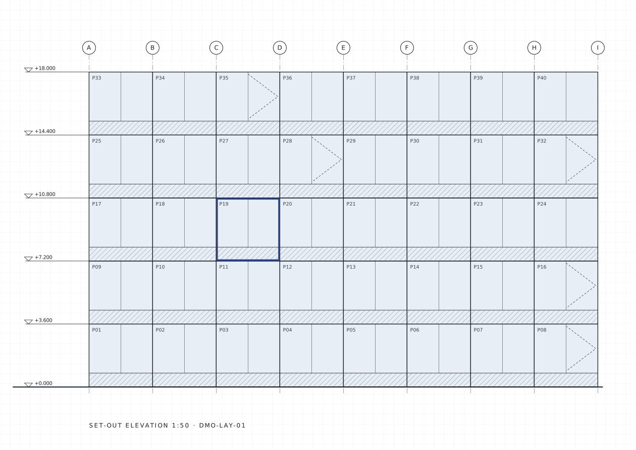
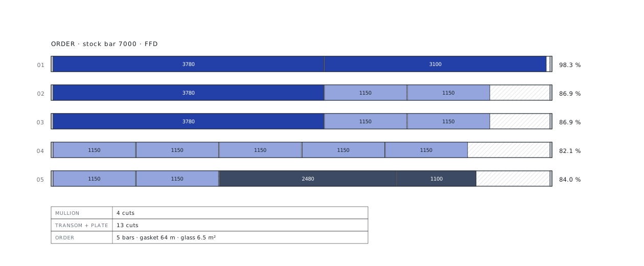
Forms and lists come ready too
A seven-tab order: bar-optimised profiles, with gaskets in metres, accessories in pieces, glass in m².
| Item | Description | Unit | Qty | Note |
|---|---|---|---|---|
| PR-D50 | Mullion 50 × 150 | cuts | 4 | 3 bars · 7000 |
| PR-K50 | Transom and pressure plate | cuts | 13 | 2 bars · 7000 |
| FT-01 | Glazing gasket, inner + outer | m | 64 | Vulcanised corners |
| AK-12 | Transom connector set | set | 16 | |
| CM-28 | IGU 6 + 16 + 6 | m² | 6.5 | 2 pcs |
| SP-01 | Spandrel: enamelled glass + stone wool + galvanised tray | m² | 2.6 | Confirm colour |
Rules applied to every set
The rules come from 19 years of facade fabrication and from approved sets. Each rule is numbered and linked to the code and to the check report.
- Sections from the supplier's own drawings; no schematic or box profiles; nodes include gaskets, silicone, blocks and screws.
- Glass line by line; a thermally broken profile is one composite item.
- Frame 45° mitred; transoms butt-jointed + notched + screwed; setting blocks 100 / 150 mm.
- Stone wool drawn with the quilt symbol.
- Readable scales: nodes at 1:2, at most two per sheet; full sections at 1:5 with break lines.
- Anchors drawn with real geometry: slots, serrated washer, fixed and sliding points, separator; a separate detail sheet.
- Unverified sections are flagged and stay on the "needs checking" list until confirmed against the catalogue.
- Set-out sheet at 1:50; plans carry three dimension rows: module, panel width and panel code.
From sketch to order in a day
Once the system data is set up, all outputs for a new sketch take minutes. The first system set-up (catalogue map, section extraction) takes 1–2 days.
* Times are estimates. This robot keeps growing with new jobs; first jobs are run together with an engineer.
Whose work this robot makes easier
- 01
Estimating and engineering teams
A fast system model with real sections from a sketch.
- 02
Small and mid-size stick jobs
Shop drawings, fabrication and ordering in one go.
- 03
Purchasing and workshop
An optimised bar order and a workshop cutting list.
- 04
Presentations to facade consultants
Readable sheets with real nodes.
Send your first file to the robot
Send one assembly, one sheet type or one bid package. We send back the sample output and a quote for the full job.
- 01Your first file is processed free of charge as a sample.
- 02After reviewing the output you get a quote for the full job.
- 03Your files stay confidential and are used for your job only.
- 04We can work with your own title block and layer standard.
Frequently asked questions
I only have a grid-and-level sketch. Is that enough?
Yes, together with the system choice and glass/spandrel assumptions. For real sections we need the supplier's profile section drawings.
Are the profile sections real?
Mullion and transom are taken one-to-one from the supplier's section drawing. Other sections are flagged "needs checking" until verified.
Does it check glass weight?
Yes. It runs the supplier's setting-block calculation tool on a copy; if the limit is exceeded it proposes a different block or a detailed calculation.
How is ordering waste handled?
Profiles are optimised over the stock bar length; gaskets are computed in metres, accessories in pieces and glass in m².
Are doors and leaves included?
Doors are drawn as an opening with a frame outline; the leaf is a separate system and stays out of scope, stated clearly in the list.