Angle Bracket Robot
From a model that holds nothing but 3D solids, with no lines and no dimensions, it produces A3 fabrication sheets for L angles and plates, their blanks, the sheet nesting and the laser DXF.
In training: the robot is being tested on approved past jobs. Files in this field are processed together with an engineer for now; you can still send one for a demo.
- Input
- 3D solid (DWG / STEP)
- Output
- PDF · DXF · DWG
- Example
- 426 parts · 3 sheets
- Status
- In training
From an undimensioned solid to a dimensioned sheet
Sometimes all you have is a 3D solid: no lines, no dimensions, no material or quantity. Drawing small parts like angles and packing plates from that takes hours, and any mismatch with the model only shows up in the workshop.
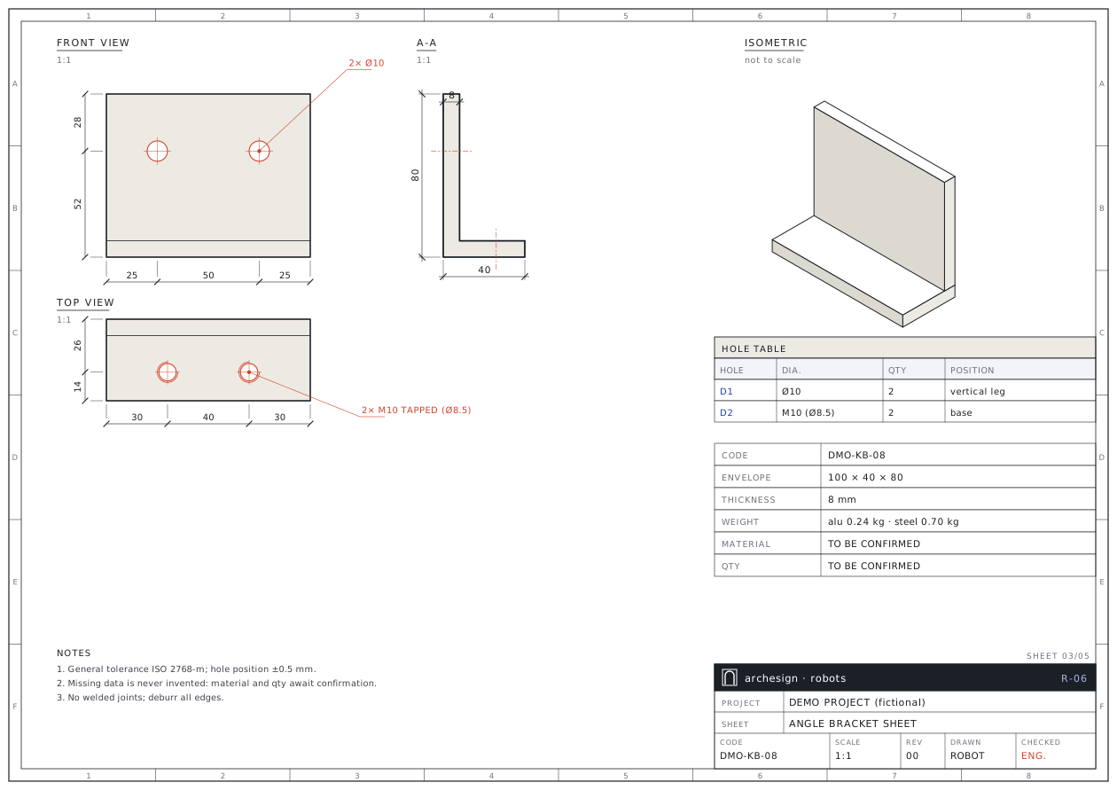
The Angle Bracket Robot reads the solid's boundary representation and extracts planes, holes, legs and wall thickness. It lays out the A3 sheet with front, top and side views, a section through the holes and an undimensioned isometric. Every value on the sheet is recalculated against the model.
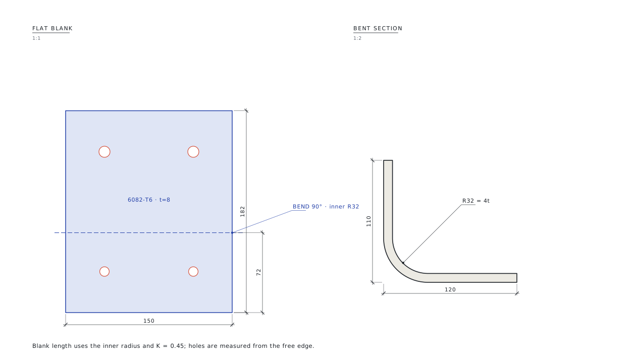
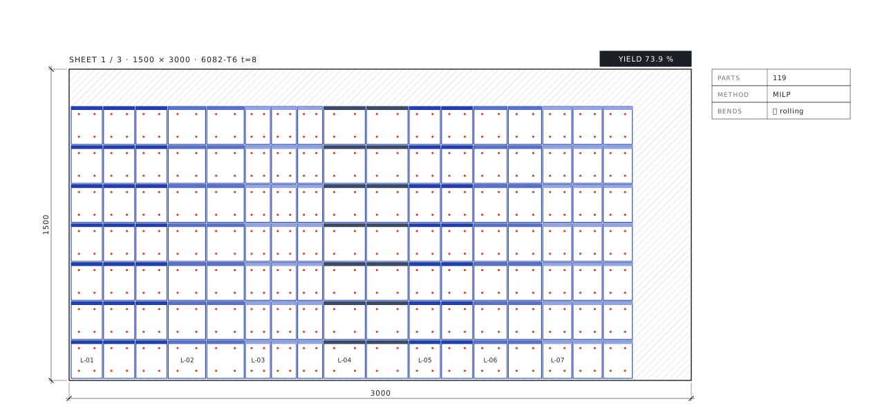
For types bent from sheet it computes the blank with the inner radius and K-factor, and produces bend lines and the laser DXF. It nests the parts on the sheet and can fill leftover space with equal extra parts of every type.
What you send, what you get back
Your files come in as they are; the output goes out in the form the workshop, purchasing and site teams use directly.
You send
- DWG3D solids onlyWorks without lines, dimensions, material or quantities.
- STEPPart modelsOne STEP per type for the bending branch.
- XLSXType / quantity tableOrder quantities for nesting and forms.
You get
- PDFA3 fabrication sheetsFront, top and side views, section A-A, isometric, part and hole tables.
- DWGDXF / DWGPer page and as one file; standard layer set.
- NESTBlank + sheet plan1:1 laser DXF: CUT / HOLE / TAP / BEND layers.
- XLSXWork and material requestsPart quantities and sheet count.
What the robot does, step by step
Blue steps are run by the robot. The red step is a facade engineer's check, and no set is delivered without it.
Exports the solidsrobot
The drawing is opened read-only; each 3D solid is exported to a text-based geometry file and the original is left untouched.
Parses the geometryrobot
Faces, edges, planes and cylinders are read; holes and wall thickness extracted.
Seats the partrobot
Legs, envelope and hole axes are placed in a local frame; a slanted leg has its angle measured.
Draws views and isometricrobot
With back-face culling and depth sorting, so hole mouths never disappear.
Lays out and verifiesrobot
Dimensions, hole callouts and tables; every value recalculated against the model.
Computes the blankrobot
Inner R = 4t, K = 0.45; leg and hole positions from the free edge.
Nests on the sheetrobot
Column layout first, then integer programming adds equal extras for every type.
An engineer checksengineer
Material, bendability and quantities are confirmed with you.
This is what the output looks like
The drawings below come from a fictional demo project. Real client drawings and codes are never shown here.
Forms and lists come ready too
Missing data is never invented: material and quantity stay flagged until confirmed, and weight is given for both materials.
| Item | Description | Envelope | t | Holes | Alu kg | Steel kg | Material |
|---|---|---|---|---|---|---|---|
| KB-01 | Flat plate | 120 × 80 | 8 | 2 × Ø10 | 0.21 | 0.60 | CONFIRM |
| KB-02 | L angle | 100 × 40 × 80 | 8 | 2 × Ø10 · 2 × M10 | 0.24 | 0.70 | CONFIRM |
| KB-03 | L angle, slanted leg | 100 × 40 × 70 | 8 | 2 × Ø10 | 0.22 | 0.64 | CONFIRM |
| KB-04 | L angle, long | 160 × 40 × 80 | 8 | 3 × Ø10 · 2 × M10 | 0.39 | 1.13 | CONFIRM |
Rules applied to every set
The rules come from 19 years of facade fabrication and from approved sets. Each rule is numbered and linked to the code and to the check report.
- Nothing is invented: material, quantity and finish stay "to be confirmed".
- Weight for two materials: aluminium and steel are both given, to make the decision easier.
- Tapped and plain holes apart: tap drill size stated; separate layer in the laser DXF.
- Sharp inner corner note: extrusion or machining assumed; if it is to be bent, the radius needs approval.
- Bendability warning: a suitable alloy and inner radius are proposed for thick sheet.
- Bends are placed across the rolling direction.
- Values recalculated against the model; any deviation stops the sheet.
- Hole dimensions in every view; the Ø label sits on the part face.
A dimensioned set in minutes
A four-part solid model became a five-page set; on an eight-type bending job the blanks, sheet plans and laser DXFs came out together.
* Times are estimates; nesting optimisation takes seconds to minutes.
Whose work this robot makes easier
- 01
Facade and precast firms
Sheets for in-panel connection parts straight from the model.
- 02
Laser and press-brake shops
1:1 DXF with tapped holes on their own layer.
- 03
Purchasing and planning
Sheet count and yield before ordering.
- 04
Design offices
A dimensioned, verified version of an undimensioned model.
Send your first file to the robot
Send one assembly, one sheet type or one bid package. We send back the sample output and a quote for the full job.
- 01Your first file is processed free of charge as a sample.
- 02After reviewing the output you get a quote for the full job.
- 03Your files stay confidential and are used for your job only.
- 04We can work with your own title block and layer standard.
Frequently asked questions
I only have a 3D solid, no dimensions. Is that enough?
Yes. Dimensions are read one-to-one from the solid's boundary representation, and the values on the sheet are verified against the model.
What if the material is not decided?
The sheet carries a "to be confirmed" note and weight is given for both aluminium and steel.
Can the parts be bent from sheet?
Yes. Blanks with inner radius and K-factor, bend lines and a 1:1 laser DXF are produced, with an alloy recommendation for thick sheet.
How many sheets will it take?
Nesting optimisation gives the sheet count and yield, and can fill leftover space with equal extra parts of every type.
How are tapped holes kept apart?
With their own callout and their own layer in the laser DXF; the tap drill size (e.g. Ø8.5 for M10) is stated.