Aluminium Anchor Robot
Draws anchor plates cut from an extrusion from the profile's own die drawing, measures slot and hole positions from the model, and produces the sheets, length-cut optimisation and request forms.
- Input
- Die DWG + STEP
- Output
- PDF · DWG · XLSX
- Example
- 440 parts · 22 lengths
- Status
- Ready
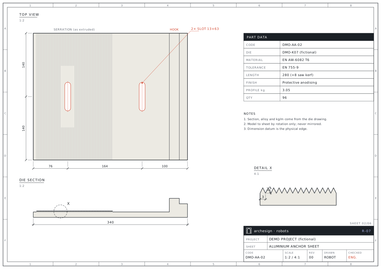
Section from the die, position from the model
Serrated, hooked aluminium anchor plates come from a dedicated extrusion die and are cut from lengths. In the model, the section is often made of approximated surfaces; teeth, tolerances and weight cannot be trusted.
The Aluminium Anchor Robot takes section, alloy, tolerance and weight per metre from the die drawing. From the model it only measures length, cut direction and slot/hole positions. It matches the part to the die, moves the slots into die coordinates and draws the sheet with the die's own outline.
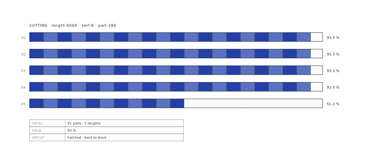
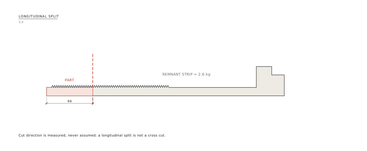
It nests the parts into 6-metre lengths and computes the number of lengths, yield and offcuts including saw kerf. For a part split lengthwise, the weight of the remnant strip goes on the sheet as well.
What you send, what you get back
Your files come in as they are; the output goes out in the form the workshop, purchasing and site teams use directly.
You send
- DWGDie drawingSection outline, alloy, tolerance and kg/m; the single source of truth.
- STEPPart modelsOnly for length, cut direction and slot/hole positions.
- XLSXBOMAnchor summary and set quantities, checked against the project total.
You get
- PDFPart sheetsTop view with serrations and slots, die section, enlarged serration and slot details.
- NESTCut optimisation6 m length patterns per die, yield and offcut list.
- DWGPDF / DXF / DWGA 4–6 page set; measurable 1:1 DXF.
- XLSXWork and material requestsNumber of lengths, stock code, part quantities and weight.
What the robot does, step by step
Blue steps are run by the robot. The red step is a facade engineer's check, and no set is delivered without it.
Processes the dierobot
The die drawing is read; outline and title-block data (alloy, tolerance, area, kg/m) are stored once in a profile module.
Measures the modelrobot
The part envelope is measured the right way; a triangulated box is never used because it inflates the size.
Matches to the dierobot
Axis, mirror and cut candidates are tried; similarity ≥ 97 % means a die part, otherwise it falls back to a generic sheet with a warning.
Measures the cut directionrobot
A lengthwise split is not a cross cut; the direction is never written unmeasured.
Moves the slotsrobot
Slots and holes go into die coordinates; a slot is verified by its area, not its bounding box.
Rotates onlyrobot
Hook on top, serrated face up; model to sheet is a rotation, never a mirror.
Optimises the lengthsrobot
6 m stock, 8 mm kerf; number of lengths, yield and offcuts. Stock is checked read-only.
An engineer checksengineer
Quantity interpretation, cut direction and finish are confirmed with you.
This is what the output looks like
The drawings below come from a fictional demo project. Real client drawings and codes are never shown here.
Forms and lists come ready too
The description states the length with saw kerf; the material form lists the number of lengths to draw from stock on its own row.
| Item | Description | Die | W × L | Qty | kg/pc | Sheet |
|---|---|---|---|---|---|---|
| AA-01 | Plate 280 (+8 kerf) | DMO-K07 | 340 × 280 | 96 | 3.05 | 02 |
| AA-02 | Plate 300 (+8 kerf) | DMO-K07 | 340 × 300 | 64 | 3.27 | 03 |
| AA-03 | Strip plate 280, split lengthwise | DMO-K07 | 66 × 280 | 120 | 0.74 | 04 |
| LENGTH | Profile length 6000 mm (from stock) | DMO-K07 | — | 15 | — | 05 |
Rules applied to every set
The rules come from 19 years of facade fabrication and from approved sets. Each rule is numbered and linked to the code and to the check report.
- The die drawing rules: section, alloy, tolerance and kg/m come from it; the model only gives position and length.
- A long hole is a SLOT; round ends, never called a "hole" or "notch".
- Serrations drawn from the die; shown enlarged and in the top view, never machined.
- The datum is a physical edge; the hook side is marked on the sheet.
- Rotation only, no mirror; asymmetric parts get a "flipped = mirrored" note.
- Profile weight is stated, not assembly weight; the unit is a "length".
- If a quantity can be read two ways, both options are asked with their consequences.
- Adding a die is one rule line and one profile definition.
A day's work in a few minutes
Five part types and about 440 parts fitted into 22 lengths at 93 % yield; a six-page set.
* Times are estimates; other figures are rounded from a real job.
Whose work this robot makes easier
- 01
Facade firms with their own dies
Define a die once; later jobs are ready.
- 02
Profile cutting shops
Cutting lists with length patterns and kerf.
- 03
Production planning
Lengths to draw from stock, and offcuts.
- 04
Quality
Die tolerance and finish note on every sheet.
Send your first file to the robot
Send one assembly, one sheet type or one bid package. We send back the sample output and a quote for the full job.
- 01Your first file is processed free of charge as a sample.
- 02After reviewing the output you get a quote for the full job.
- 03Your files stay confidential and are used for your job only.
- 04We can work with your own title block and layer standard.
Frequently asked questions
Why the die drawing and not the model?
Model surfaces are approximated and the teeth get distorted. The die drawing is the official source for section, alloy, tolerance and weight; the model is only used for position and length.
How do you prevent a flipped or mirrored part?
Model to sheet is a rotation only; mirroring is never used. Asymmetric parts also get a warning note.
What does the optimisation consider?
Stock length, saw kerf and part quantities. The output gives the number of lengths, yield and an offcut list; identical patterns are grouped on one line.
How is a new profile added?
The die drawing is processed once and a line mapping part names to the die is added. Later jobs reuse it.
Does it check stock?
It suggests a read-only check against your stock list; the form states the lengths to draw from stock. Nothing is written to your systems.